| Label :
|
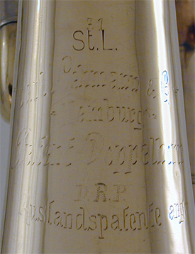
31 St.L. Carl Lehmann & Co. Hamburg Patent Doppelhorn DRP Auslandpatente ang |
||
|
Model:
|
"Walzen" Compensating |
||
|
Serial Number:
|
31 |
||
|
Date of Manufacture:
|
ca. 1925 |
||
|
Key(s):
|
F and B♭ | ||
|
Valves:
|
3 rotary and 1 "Walzen" |
||
|
Bore:
|
11.90 mm. |
||
|
Bell Flare:
|
wide (90 deg.) vee gusset |
||
| ca. 6.3 cm. |
|||
|
Bell Diameter:
|
31.6 cm |
||
|
Base Metal:
|
yellow brass |
||
|
Finish:
|
raw brass |
||
| . (click on photos for larger view) |
|||
 |
 |
||
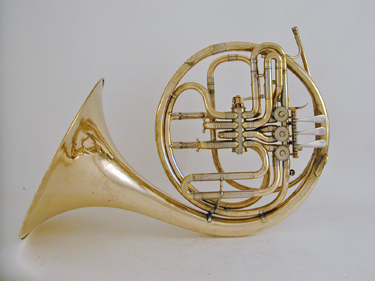
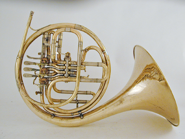
The compensating double horn by Carl Lehman & Co. shown above is a fine example of a "walzen" horn. The term "walzen" (German for roller, barrel, or drum) describes the large rotary change valve in the center of the horn. In this "compensating" design the B♭ slides are located between the main valves and the change valve, with additional "compensating" slides for the F horn on the opposite side of the change valve. The change valve adds proportional supplemental tubing to the B♭ slides. One advantage of a compensating horn is its lighter weight since tubing is shared between the F and B♭ slides. In addition to Carl Lehman & Co. horns of this design were also produced by the firms August Knopf, Joesf Lidl, and other makers. This horn dates from about 1925 and the label (below) states that patents are pending in Germany and foreign countries. Carl Lehman was a brass instrument maker who flourished in Hamburg from ca. 1925 to ca. 1944. Deutsches Reich Patent 440308 for a Schaltventil für Blechblasinstrumente (Switching Valve for Brass Instruments) was issued jointly to Lehmann and Erdmann Chemnintzer on November 24, 1925 with subsequent foreign patents for the same valve design in Austria (107404, October 10, 1926), Great Britain (263460, December 30, 1926), France (622,226, February 21, 1927), and the United States (1,642,783, September 20, 1927). |
|||
|
|||
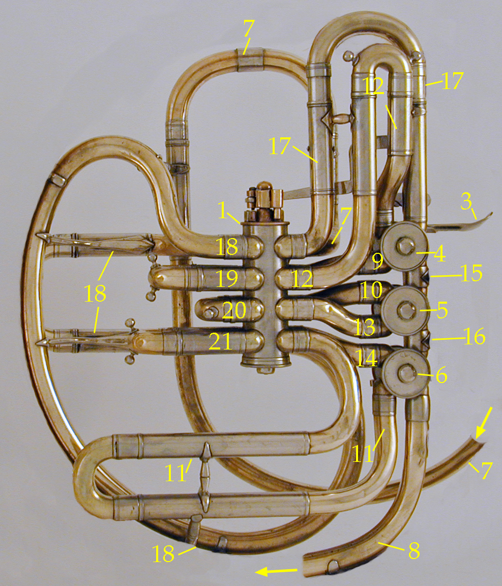 With minor differences to the wrap, the body of the horn (above) closely corresponds with the original patent drawing (right). The components are identified in the list below, right. |
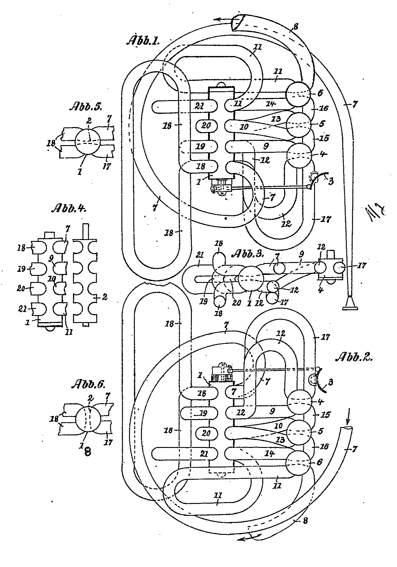 Lehman and Chemnitzer, DRP 440308, 1925 |
||
Analysis: |
Legend: |
||
|
|||